Specification
| General measurement | |
| Accuracy | Class 0.2, Class 0.5 (Frequency ± 0.01 Hz, Power Factor ± 0.1°) |
| Mains frequency | 50 or 60 Hz (45-65 Hz) |
| Measurement | True root-mean squared (RMS) |
| Voltage Circuit | |
| Nominal measuring voltage (UN) | 3 x 100-693 V (three-wire system) 3 x 57.7/100 V to 3 x 400/693 V (four-wire system) |
| Measuring range | 0% – 120% UN |
| Burden | ≤V/400k |
| Maximum overload voltage | 1.2 x UN continuously 1.5 x UN for 10 s with up to 10 repetitions at 10 s intervals 2 x UN for 1 s with to 10 repetitions at 10 s intervals |
| Starting voltage | 0.25 V |
| Current Circuit | |
| Nominal measuring voltage (IN) | 1-5 A |
| Measuring range | 0% – 200% IN |
| Burden | ≤Ix0.01 |
| Maximum overload current | 2 x IN continuously 20 x IN for 1 s with up to 10 repetitions at 100 s intervals 40 x IN for 1 s with to 5 repetitions at 300 s intervals/td> |
| Starting current | 4 mA |
| Auxiliary Supply | |
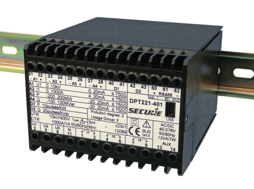
| Voltage range | e 40-276 V AC or DC (AC frequency 45-65 Hz |
| Maximum burde | n < 12 VA / 7 |