Choose another country or region to see content specific to your location.

Product at a glance

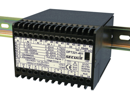
Our family of DIN-rail programmable transducers (DPT) measure a wide range of electrical parameters and generate equivalent analogue output signals suitable for interfacing with instrumentation and control systems. DPTs are available with up to four analogue outputs, up to two digital outputs and Modbus communication functionality. All the outputs are galvanically isolated and can be programmed with easy-to-use ConfigView software. Any of the measured parameters can be assigned to the analogue outputs and can be read out via the optional Modbus connection. ConfigView can also be used to configure the connection to the measured circuit for single-phase, three-phase three-wire, three-phase four-wire, balanced or unbalanced load. DPTs comply with IEC 60688 and are available in accuracy classes 0.5 and 0.2. DPT support wide range of voltage, current and auxiliary supply.

Application

  • Instrumentation panels
  • Control systems
  • Electrical distribution panels
  • Transmission systems and generators
  • SCADA systems

Benefits

  • Each DPT covers the entire range of common electrical parameters
  • DPT decal (rating plate) configurable and printable through software
  • Better response time
  • THD measurement
  • Offered product suitable for stocking at Distributor/OEMs end
  • User friendly Configuration & Reading through Configview software
  • Easy to install and configure

Features

  • Fully programmable inputs & outputs
  • Accuracy class 0.5 or 0.2
  • True root mean squared (RMS) measurement
  • Up to 4 analogue outputs (voltage or current signals)
  • Up to 2 digital outputs only for energy parameters
  • Optional Modbus communications via RS-485 port
  • DIN-rail mounting
  • USB Mini port for local programming
  • Meter cover and terminal cover open detection
  • RS232 port compatible with meter-powered modem

Specification

General measurement
Accuracy Class 0.2, Class 0.5 (Frequency ± 0.01 Hz, Power Factor ± 0.1°)
Mains frequency 50 or 60 Hz (45-65 Hz)
Measurement True root-mean squared (RMS)
Voltage Circuit
Nominal measuring voltage (UN) 3 x 100-693 V (three-wire system)
3 x 57.7/100 V to 3 x 400/693 V (four-wire system)
Measuring range 0% – 120% UN
Burden ≤V/400k
Maximum overload voltage 1.2 x UN continuously
1.5 x UN for 10 s with up to 10 repetitions at 10 s intervals
2 x UN for 1 s with to 10 repetitions at 10 s intervals
Starting voltage 0.25 V
Current Circuit
Nominal measuring voltage (IN) 1-5 A
Measuring range 0% – 200% IN
Burden ≤Ix0.01
Maximum overload current 2 x IN continuously
20 x IN for 1 s with up to 10 repetitions at 100 s intervals
40 x IN for 1 s with to 5 repetitions at 300 s intervals/td>
Starting current 4 mA
Auxiliary Supply
Voltage range e 40-276 V AC or DC (AC frequency 45-65 Hz
Maximum burde n < 12 VA / 7
For more details click here.